Saturday, November 20, 2010

Installing the Plywood


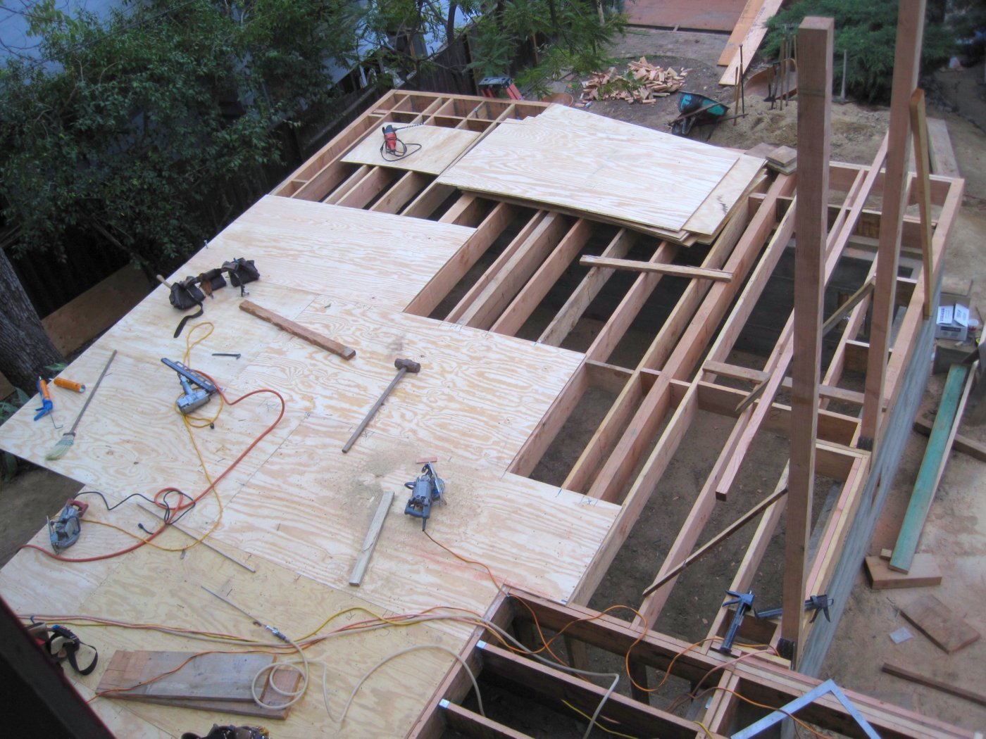
After the floor is framed, blocked and all the hardware is attached it's time to attach the plywood.


The plywood went on in lightning speed...A few boards needed some nudging.  The plywood is T&G (Tongue and Groove) so that it holds together better and doesn't settle differently.  When the plywood has square edges there is a better chance that the seams can end up at slightly different heights over time.


Two guys hold the seam together by standing on it while the third knocks it  into the groove...


The Structural Engineer specified the spacing of the nails in the drawing set  that the crew has to follow - this floor is nailed in at 6" centers around the perimeter and 10" centers at the intermediate joists.


cRim
e scene - 1


Unfortantely, the girls were so upset that the addition did not include their bedroom that they jumped out the second story window...

Wednesday, November 17, 2010

Floor Framing

The crew has been framing the first floor the past few days.  There is a lot of hardware that gets installed which makes the floor framing take longer.  The perimeter beams are on top of the anchor bolts and needed to be notched at each location.  And the Structural Engineer is calling out for a lot of "hold downs."  The hold downs are heavy steel anchors that get bolted to the sole plate and beams so that they all move together in case of an earthquake.  That is probably the biggest difference between the older houses and the ones that go up today.  


view from crawl space below

floor framed...


Lower Level Floor Plan

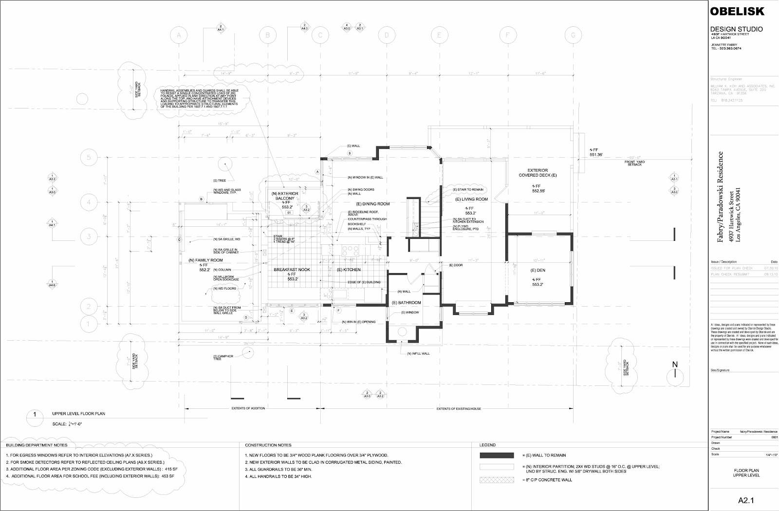
Upper Level Floor Plan


The crew has also been stacking up the materials  that are going to be hauled from the site....


and finally...the big pile gets thrown over the side of the garage via a ramp to the hauling truck waiting below...yay!


"ELLAHARPERBEA"

Thursday, November 11, 2010

Backfilling and Framing

They finished removing the remaining form work on Tuesday and have started the process of backfilling the remaining trenches.  Only the excavated decomposed granite can get put back in and it has to be placed so that it can regain it's density and therefore strength.  The granite is placed into the trenches in what is called 2' 'lifts'.  That means that only 2' high of soil is placed at a time, it is wetted with a little water to help it settle and hold better and then it is pounded by a mechanical device called a compacter.


The old formwork boards are scraped and
 the nails removed so that they can be
re-used for another pour.


shoveling dirt from the big pile to the inside of the walls


finished walls, stripped of formwork


       compacting the soil


The first piece of framing to go on is called a sole plate - it is pressure treated lumber that has been designed to be placed against the concrete which will always have a little moisture in it and could rot untreated wood.  Here Chillo pre-drills holes into the plate that match the bolts that were cast into the concrete.

The sole plate going onto the wall


The last of the form ties are getting snapped off so that they won't be 
visible any more.

The plate gets attached to the wall - a large steel square washer and nut are placed onto the sole plate and the nut is tightened by mechanical tool so that it reached the right torque.


this what the sole plate, bolt, washer and nut looked like when they're all assembled - they are placed 18" on center


A cripple wall is a short wall...here Chillo is building a
cripple wall that extends from the new floor height to
 the existing floor height - there is a 2' difference.
He is also using a jack to lift the house a
little in spots where it has settled.
He can only jack it up a bit or else the windows which have
settled with the walls over the years will pop and break.

Bea and Sofie 


Thursday, November 4, 2010

Cast-In-Place Walls

This week the crew finished constructing the board form for both sides of the cast-in-place walls, added all the bracing to support the walls during the pour and placed the anchor bolts on the top that will be cast into the concrete during the pour - and passed three inspections - and poured!  Phew...


            Here is a view of one of the walls with both sides of formwork on before they placed the anchor bolts on top.

view down one of the tall walls to the footing


Here is a view from the North before and after the concrete was poured....you can see some of the concrete starting to ooze out between the boards.  We wanted 'board-formed' concrete walls.  There are a lot of different ways to make the formwork for a cast-in-place wall and they all result in a different looking wall.  The boards will leave an imprint on the concrete and because there is a small gap in-between each board some concrete spills out to give the wall a little texture.

after pour


West wall after pour...

View from above...


Today they have to let the concrete set - tomorrow they will start taking off the formwork so that it doesn't stick to the concrete.  By Monday the concrete will be strong enough so that they can start back filling the trenches with the large pile of bedrock that was excavated for the footings.  They have to put the bedrock back in small increments and tamp it down with a machine that vibrates and compacts it.  By code the final compaction needs to be 95% or more meaning that it is very dense and will add support to the vertical stem walls.  The rest of the soil that was considered fill will need to be exported from the site and thrown away.


Thursday, October 28, 2010

Progress on stem wall forms and rebar layout

Today they finished the formwork on one side of each stem wall.  The crew also made a lot of progress with the rebar steel.  The engineer dictates the spacing of the rebar and it is based on the height of the wall and the loads it will take.  He has asked for #5 bars for the verticals.  You can figure out the diameter of the rebar steel by taking the # and dividing it by 8; the #5 bars are 5/8" in diameter.  He has detailed them to be 16" on center.  16" will recur over and over in the structure of the house because all american products are based on typical dimensions that are evenly divisible by 16" to minimize waste.  For example, plywood sheets are 48" and 96".  The horizontal bars are #4's (1/2" in diameter.)  To minimize waste and (if you're interested) save money on a project you can base you're dimensions with this in mind.  For example wood studs come in 8', 10' and 12' lengths or any length over that if they are special ordered.  If you can stick with the 8' stud they are a lot cheaper than the 10' stud...and so on.


view of formwork (one side done) and rebar...

As the Architect we have dictated the layout of the walls based on where we want them relative to the floor above.  In some places we wanted to minimize the apparent height of the wall so we held the foundation wall in from the footprint of the building above.  In those places the building will cantilever a couple of feet and create a visual break and a shadow.

We also have several openings in the wall that were dimensioned on the Architectural Exterior Elevations.  Some of the openings are for ventilating the crawl space below the house and are required by our local building code.  We had to calculate the square footage of crawl space and provide ventilation based on a percentage of the area below the house.  Other openings are for access and for equipment.


The photo on the left is of the rebar layout at the West wall.
The photo on the right is a detail of the opening.  They will attach wood block outs to the formwork so that concrete does not get into this area.


The large opening is for access to the crawl space under the house and also for a new furnace for the addition.  The new furnace will be 93% efficient using very little energy and qualifying us for a rebate from our local gas company and also a 30% tax credit...yay


Some walls already have the formwork on both sides and rebar done.  The two form walls get connected by "ties."  The ties keep the walls connected during the pour so that the weight of the concrete doesn't bow them or make them actually blow out.  There are many many different types form ties and they create different looks on the exterior wall and also have different structural strengths.  For very large, heavy thick walls the engineer and architect may need to spend a lot of time making mock-ups of the effect of different ties.  Ours are pretty minimal and won't be very visible on the final wall.  When you see what look like evenly spaced holes on a large concrete wall those are the marks of the ties that were used to hold the formwork.


At the top of the wall the concrete will be connected to the wood framing by a "sill plate" and "anchor bolts."  The sill plate is a very thick piece of wood that has been treated against rot and insects by infusing it under pressure in a bath of chemicals.  To connect the sill plate to the concrete a hole is drilled in the sill plate and a long bolt with a "j" shape is hung from the sill and held in place by a thick square washer.  The anchor bolts are spaced such that every third one gets tied with wire to the vertical steel.  In this way the wood and concrete are stiffly connected which protects our houses in California from literally "jumping" off of their foundations.  Because we are subject to more than just gravity here our engineers have to account for lateral and vertical loads also!


Our addition is 2' lower than the original house so that it steps with the hill...here is a photo of the footing stepping...

...and Bea taking a last peak below the house.


If all goes well the crew will wrap up the steel placement tomorrow get it inspected by three different people and then pour by Wednesday....